
- Approved Project Quality Plan
- Approved Project HSE Plan
- Approved Material Management Plan
- Approved Material Submittal for Cable Management (Tray, Ladder & Trunking)
Following tools shall be arranged before starting the installation of cable tray and trunking on the site:
- Mini Hacksaw Frame with Blades
- Measuring Tape
- Grinder with cutting disc
- White chock /Marker
- Sprit Level/ Water Level Pipe
- Point & Flat Chisels
- Ladder / Scaffolding.
- Generator / Power source
- Ladders / Scaffolding
- Drill Machine
Roles and Responsibilities
Project/ Construction Manager shall be responsible for the overall implementation of this method statement, and to ensure that section engineer and general foremen are well informed of its requirements. He is responsible for:
- Providing all required resources in terms of manpower, equipment and material.
- Controlling the coordination between all involved parties to ensure that the applicable HSE, Quality and schedule requirements are met.
Section Engineer and General Foreman in-charge shall be responsible for:
Controlling and ensuring the construction work is carried out in accordance with the required contract specifications and approved shop drawings.
Implement the PTW as required by client and company’s own HSE procedures.
Notifying QC engineer and issuing the WIR (request for inspection) timely manner (normally 24 hours in advance) when work is ready for inspection as detailed in the relevant ITP.
Liaison with client/consultant’s MEP engineer for any coordination requirements depending upon the site conditions.
Accompanying the quality engineer and consultant during the ongoing site inspections to obtain his approval and to proceed the works smoothly.
Site Quality Manager shall be responsible for:
Reviewing all relevant documentation and test reports and prepare all handing over dossiers.
Clearing all non-conformances relevant to the cable tray installation activity.
Ensuring that all activities subject to inspection are recorded and cleared.
Controlling and organizing the inspection works.
Ensuring that inspections are carried out timely and in proper manner.
Quality control engineer ( QCE) shall be responsible for:
Inspecting and ensuring the construction work is carried out in line to the required contract specifications and approved shop drawings
Informing the consultant via (WIR) Work Inspection Request when his presence is required to carry out the inspection as per the approved ITP.
Accompanying the client for inspection to release the hold points.
Health, Safety & Environmental HSE Requirements
Prior to commencement, all activities shall be coordinated with the project HSE officer and PTW holder, who will assess the associated risks if any, and monitor the implementation of the work as per the project HSE plan and liaise with the construction team to ensure safe working environment all the time.
HSE Safety officer in charge shall ensure that all workers are equipped with necessary PPE throughout the cable tray installation work. He shall coordinate with the construction manager to study, organize and control the traffic flow during the implementation of this working procedure.
Construction manager in coordination with the safety officer, store/time keeper and camp boss shall conduct an induction session for all staff and workers involved with this particular operation to ensure every person is well aware of his obligation, work distribution and role.
Safety officer shall organize and conduct necessary periodic toolbox meetings for supervisory staff and manpower, to ensure the construction team are well aware of safety requirements.
All lightings shall be provided as required and manpower schedule shifting incase the works went beyond the normal working hours.
Prior To Start Work
PTW must be secured before starting the work
Install the Necessary barricades and signages.
Ensure that the work area is ready and safe to start the installation of Cable Tray, Ladder, Trunking and its accessories.
Sequence of Work
Check all material delivered to site is inspected properly by QA/QC engineer, approved and it is stored properly.
MIR shall be raised for the inspection of materials, Cable tray, Cable Ladders, Trunking and its accessories, received at site to the consultant.
Work shall be carried out by the site staff under strict supervision and guidance of the concerned Supervisors / Foremen / Engineers.
MEP QA/QC Engineer shall check all the installations as per the installation check list.
WIR shall be prepared by MEP QA/QC Engineer and will be submitted to consultant for their inspection and approval.
QA/QC Engineer shall coordinate with other contractors and arrange inspection for installation to the consultant.
MEP QA/QC Engineer is responsible for all installation activities for getting the work inspected and approved by consultant.
Cable Tray Installation Methodology
Ensure that the approved shop and coordination drawing are ready as per site requirement for MEP services and working place released for electrical works i.e. civil clearance is obtained.
Make sure that cable tray is of perforated type and constructed by using hot dipped galvanised mild steel for outdoor damp conditions.
Mark the location of cable tray based on approved shop drawings and coordination drawings.
Make holes using suitable drill bits and insert the rawl bolts for hanging the supports.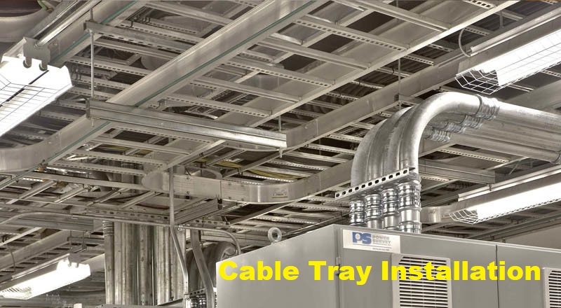
All cable trays shall be installed in a straight run parallel to walls where possible.
Ensure the cable weight coming on cable tray and accordingly decide the necessary support and support accessories, cable trays shall be supported by electro-galvanised STRUT Type channel with galvanised threaded rod for indoor suspended cable tray.
Refer approved drawings and details for sizes and routes etc.
After completion of supports, fix the cable tray with the help of spring nut on the channel.
Check the level of cable tray and recheck the size of tray which should be as per approved drawing for cable tray layout.
Cable Ladder Installation Method
All cable ladders and accessories installed indoors shall be heavy-duty hot dipped galvanized mild steel type.
Cable ladder shall have a 150 mm high longitudinal side member for ladders width of 800 mm or above and 120 mm high longitudinal side member for ladder width less than 800 mm.
The rungs shall be at least 50 mm wide, with slots of 25 mm x 10 mm at 25 mm intervals covering the length of the rungs, the rungs shall be spaced at 300 mm apart along straight lengths of the ladder.
All nuts, bolts and washers for clips and brackets shall be zinc plated.
Each cable ladder shall be in standard manufacturer’s length and supplied complete with coupling sets consisting of fishplates, nuts and locking washers.
The complete cable ladder installation shall be provided with all necessary proprietary factory made elbows, risers, reducers, tees, crosses, drop-outs, etc.
Separate flexible earth continuity connectors of at least 16mm² copper jumpers shall be installed between the ladder sections.
All cable ladders shall be supported from the ceiling concrete slab, steel structures or sidewalls using a frame system similar to UNISTRUT, with overhead hangers, support channels, threaded rods or angle brackets, beam clams and ceiling brackets.
Fixings and supports shall be installed at regular intervals not exceeding 1000 mm and 150 mm from all bends, tees, inter-sections and risers.
When cable ladder is refined to install across structure expansion joints, the ladder shall be in two sections between supports installed on either side of the expansion joint.
The ladder sections shall than be jointed with expansion joint fishplates, bolts, nuts and washers installed in elongated holes permitting a lengthwise movement of 25 mm from the initial fastening position.
Braided Copper earth link shall be fixed at every joint of the cable ladder run.
Installation of Cable Trunking
Cable trunking shall be manufactured from electro-galvanised mild sheet steel to BS4678 finished in oven-baked electrostatically coated epoxy power coating with color as per the clients choice.
All trunking shall have removable lids extending over their entire lengths.
Lids shall be fixed at interval not exceeding 1 metre by means of brass steel screws which are protected against corrosion by a finish of zinc coating or equivalent to zinc coating.
Fire barriers shall be provided within the trunking at each crossing of fire wall or fire zone.
Installation procedure
Ensure that the coordination drawing is ready as per site requirement for MEP services and civil clearance is obtained to start the cable trunking installation.
Mark the location of cable trunking based on coordination layout drawing.
Mark for fixing supports and make holes in slab/wall with the help of concrete bit.
After completion of support fix the cable trunking on that channel.
Size of cable trunking should be as per approved drawing for cable trunking layout.
Check the level of cable trunking.
Paint the cut edge of cable trunking with aluminium galvanized paint.
Purpose made bonding link bar shall be fixed at every joint of the cable trunking run.
Use correct fitting on risers and bends.
Spares and Installation Space Factor
Sizing of cable trays shall be such that there will be 30% spare capacity for future cables.
Space factor for the conduits, trunking, etc. shall be in compliance with latest IEE wiring regulations (BS 7671) and shall not exceed 40%.
Trunking space factor shall be in compliance with BS7671 and 25%.
Installation Checklist for Cable Tray Installation
Check Layout.