
Below is a precise mechanical method of statement that covers installation, testing and commissioning of Building Management System BMS to ensure that the site installation work execution complies with the project requirements and serves the intended function to satisfactory level.
Required Tools:
- Standard electrician & wireman tools
- Portable hand tools
- Spirit Level / Level Threads
- Digital multimeter
Material Handling & Storage
On receipt of the BMS System accessories at site, necessary precautions shall be taken for unloading, shifting & storage, as follows:-
All packages for the complete set of BMS System, reaching to site shall be identified as per package list.
Where auxiliaries are shipped loose, these will be identified and checked against the dispatch documents. Any item found missing or damaged will be noted to the supplier immediately for the replacement / repair.
Special attention shall be paid to the instruments and monitoring devices supplied loose.
All materials received at site shall be inspected and ensured that the materials are as per approved material submittal, shop drawing and single line diagram.
Any discrepancies, damage etc., found will be notified and reported for further action.
Site Engineer (Electrical) has to ensure that material used at site are of free from any damage
All packages shall be stored under protected dust area.
BMS Installation Preparation & General Requirements
Ensure all civil works are completed for the area to carryout the installation, and clearance is
obtained from respective authorities to proceed further.
Prior to start the installation, refer to the approved shop drawings related to the area of
installation and ensure that required materials are available at site as per approved material
submittals.
Ensure the materials are stored properly and there is no mark of damage or deformity of any
kind before issuing the material from site store.
All shop drawings, riser diagram must be approved by supplier and consultant for all installation methods and details.
Ensure that all outlets related to BMS are in accessible area and not covered by MEP services.
Ensure that work area is ready and safe to start the installation of BMS System.
Ensure that as built drawings showing all changes are ready before false ceiling finish.
Ensure the installation of BMS System and accessories are carried out in accordance with manufacturers installation recommendations, requirements of applicable standards and in accordance with recognized industrial practices, and specified in project specification to ensure that installation complies with requirements.
BMS Installation Procedure
The Installation consists of the following stages which are covered below: –
- Conduiting and cabling
- VAV, FCU Controllers
- Control valves and actuators
- DDC panels and Field devices
Conduiting and Cabling:
PVC conduiting / GI conduiting or trunking shall be done as per approved shop drawing to pull control wires for all field devices and control panels.
Installation of VAV, FCU Controllers with Field Devices
- The Controllers, transformers and relays shall be delivered by the system supplier.
- These Controllers shall be mounted with an enclosure with control transformer attached to VAV control assembly.
- Two Port valve with actuators shall be installed in the chilled water CHW pipes at FCU’s as per approved shop drawings.
- Control Wires to be pulled between the VAV, FCU’s controllers and thermostats, two port valves as per approved wiring drawings.
- Terminations at VAV controller shall be carried out as per company approved method statement for wiring.
- After final wall finishes room thermostats to be installed and terminated.
- Thermostat unit shall be fixed with inbuilt jack and laptop connection can be made with the existing control cable wiring.
Installation of Direct Digital Controller (DDC) with Field Devices
The preassembled DDC Control panel with Controllers, modules, transformers, relays shall be delivered by bms system supplier.
Control panel shall be installed with required power supply on the wall as shown in approved shop drawings and to be coordinated with other services.
Conduiting / trunking to be installed between the field devices and the control panel.
For HVAC Equipment’s, field devices pertaining to ducting like temperature sensor, humidity sensor, motorized damper actuators, are to be installed and terminated as per manufacturers recommendations.
Field devices pertaining to CHW chilled water pipes like CHW temperature sensor, pressure sensor and flow sensors are to be installed and terminated as per manufacturers recommendations.
Wiring and connections for all field devices shall be done as per the approved BMS point schedule, wiring schedule and schematic diagrams.
Field devices like outside air humidity sensor, water level sensor, staircase pressurization sensor shall be installed and connected as per approved BMS system.
VFD’s are fixed inside AHU control panels and required cable connections shall be done as per approved schematic diagrams.
Conduiting and wiring for plumbing systems like Water Booster Pump sets, fire pump sets, water Calorifier, pump to be carried out from DDC panel as per system requirements.
Terminations at field ends shall be carried out as per approved manufacturers recommendations.
For DDC control panels control cabling shall be done through GI conduit or GI trunking above false ceiling as per approved shop drawings, schematic drawings and all control wires shall be dressed properly with related identifications and connected as per approved data point schedule.
Central Peripherals and Integration Installation
Bus loop wiring to be carried out from the Central Controller to all the VAV’s & DDC as per the approved schematic drawings.
The pre assembled peripherals with controllers hubs shall be installed in the BMS control room.
Wiring between the central peripherals and the low current systems shall be carried out as per approved shop drawings.
Installation of Central Peripherals like Computer, Printer, Monitor shall be installed as per the approved BMS system and approved shop drawings.
Installation procedures of field devices for HVAC equipments
A- Installation of duct air temperature sensor
Installation of the duct air temperature sensor shall be as per approved shop drawings and manufacturers recommendations.
The location of the duct air temperature sensor shall be marked as per the approved shop drawings.
A hole of dia 20mm shall be made using a hole saw cutter and the mounting flange shall be fitted.
The temperature sensor shall then be inserted and installed on the mounting flange.
Sensing element shall be diagonally bent across the cross section of the duct and the end of the element shall be fitted using the collar provided with the sensor.
It shall be ensured that the sensing element is not touching the duct wall.
B-Installation of duct temperature or humidity sensor
The installation of the duct air temperature or humidity sensor shall be as per approved shop drawings and manufacturers recommendations.
Location of the duct air temperature or humidity sensor shall be marked as per the approved shop drawings.
It shall be ensured that the sensor is mounted on the middle of the duct wall.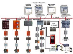
A hole of dia 22mm shall be made using a hole saw cuter and the mounting flange shall be fitted.
Temperature or humidity sensor shall then be inserted and installed on the mounting flange.
The sensor shall be installed in such a way to have elect. cable entry from down side.
C – Installation of water differential pressure sensor
The installation of the water differential pressure sensor shall be as per approved shop drawings and manufacturers recommendations.
Location of the water pressure sensor shall be as per the approved shop drawings and it shall be below the pressure measuring points.
The pressure sensor shall be installed using the GI mounting bracket provided with the sensor.
Surface of the installation of the sensor shall be vibration free i.e. not on the surface of any equipment with moving parts.
Holes of dia 5mm shall be drilled at the bottom of the pipes for pressure tapping and standard fittings supplied with the sensor shall be used for connections.
The tapping point shall be connected to the sensor using the copper capillary tube supplied along with the sensor.
D – Installation of air differential pressure sensor
Installation of the air differential pressure sensor shall be as per approved shop drawings and manufacturers recommendations.
The location of air differential pressure sensor shall be as per the approved shop drawings.
Air differential pressure sensor shall be mounted on the duct wall using fasteners supplied with the sensor.
The sensors shall be installed using GI mounting bracket provided with the sensor.
Two duct probes shall be installed, one in the suction and the other in the discharge side of the fans.
The probes shall be connected to the pressure sensor using the plastic tubing provided with the sensor.
E – Installation of immersion water temperature sensor
Thermo well shall be installed first in the chilled water pipe line and temperature sensor shall be installed inside the thermowell suitably.
The installation of immersion water temperature sensor shall be as per approved shop drawings and manufacturers recommendations.
Sensor shall be installed in such a way that the stem length is completely immersed in chilled water as per manufactures recommendations.
The sealing of the socket and the sensor threads shall be made using Teflon tape.
It shall be ensured that the cable entry to the sensor is not from the top of the sensor.
F – Installation of smoke detectors in AC ducts
Installation of smoke detector duct housing shall be as per approved shop drawing or manufacturer recommendations.
Mounting holes shall be drilled for duct housing and also holes made to insert air sampling and exhaust tubes as per manufacturers recommendations.
Wiring shall be as done for detector connection as per approved shop drawings.
The smoke detector then be installed with the base unit inside smoke chamber using the adopter plates as shown in the installation instructions.
G – Installation of butterfly valves
The installation of butterfly valves shall be as per approved shop drawings and manufacturers
recommendations.
Butterfly valves shall be installed in a sandwiched position using appropriate flanges.
Upon completion of installation and insulation of the valves , the actuators are installed.
It shall be installed that the valve actuators are not installed upside down in any case.
All the other actuator orientations are acceptable as per manufacturers recommendations.
H – Installation of two port valves
Installation of two port valves shall be as per approved shop drawings and manufacturers recommendations.
The valves shall be connected to the piping using threaded fittings or flanges depending upon the pipe diameter.
Upon completion of installation and insulation of the valves the actuators are installed.
It shall be ensured that the valve actuators are not installed upside down in any case.
All the other actuator orientations are acceptable as per manufacturers recommendations.
Manufacturer recommended installation details
A – VAV, FCU CONTROLLERS
VAV and FCU controllers consists of the following devices.
- VAV controller
- Thermostat – room unit
- Room sensor
These devices shall be installed as the approved shop drawings and as per Manufacturer’s recommendations.
B – VALVES & ACTUATORS
- Two way valve & Actuator.
- Butterfly valve, Actuator & end switch.
- Electro hydraulic actuators for valves
- Damper actuators for AHU
- Damper actuators for FAHU
C – SENSORS AND GAUGES
- Immersion Temperature Sensor
- Duct Temperature Sensor
- Duct Humidity Sensor
- Duct Air Pressure Sensor
- Differential Pressure Switch.
- Combined Humidity & Temperature Sensor
- Duct Air Quality Sensor
- Float Switch
- Level Sensor
- CO Sensor
- Flow Sensor
Specialized Products
- Expandable Controller
- BCM Power Supply Module
- BCM Ethernet Module
- BCM MS / TP Module
- Room Thermostat- FCU
- Compact Operator Terminal
- Interface Module for Chiller Management
- VAV / CAV Controller with Actuator
- FCU Controller
- Wall Mounted Sensor with set point and LCD display
Testing and Commissioning of Building Management System BMS
The purpose of this procedure is to define the step by step method to implement the correct practices for the precommissioning & commissioning of “Building Management System“.
By following the guidelines given contractor shall ensure that the job execution complies with the project requirements and serves the intended function to satisfactory level of the client.
Below is the list of required Tools before starting the BMS testing and commissioning works:
- Multimeter
- Clip on ammeter
- Portable operator’s terminal
- Lap top PC
- Electronic Temperature/ Humidity meter
- Sling pychrometer
Note : All measuring instruments shall be calibrated with valid certifices.
Precommissioning Procedure for Building Management System
Ensure that the installation of the BMS componets are complete & mechanical completion is approved & all comments on the mechanical & electrical installation inspections are incorporated.
Ensure that no damage has occured between mechanical completion & precommissioning.
Replace damaged components, if any.
Ensure the installation of BMS components are in line with the approved shop drawings & manufacturer’s recommendations.
Ensure that all the relevant system have been pre commissioned & commissioned as standalone systems.
Switch OFF all parts of the system which are commissioned.
Check all peripheral device are mounted & connected. All mechanical installation shall be visually checked for correct application / location.
Check all the wires & cables are correctly connected inside the control panels / DDC controllers & to the peripheral devices.
Check the control panel input terminals for interference voltages. Interference voltages are checked with an AC range voltmeter, by measuring the voltage at each input terminal in the control panel with respect to earth.
All control cables will be point to point tested by means of a multimeter.
Fan Coil Units: Ensure all FCU controllers (RXC 21.1) are installed & connected via communication bus.
Sensors, DP switches & control valves: Ensure that the installation of all the sensors, DP switches, valves, are completed mechanically & electrically.
Commissioning of Building Management System
AHUs, FAHUs, Fans
Application software shall be loaded into all controllers as required. Individual systems will be tested & commissioned adjusting control loops (temp control, speed control, etc.,) & programming
set points & time channels.
Individual systems will be commissioned adjusting the control loops & programing any local time programs, etc.,
Motorized valves & dampers will be stroked through 0-100%.
Temperature & relative humidity sensors will be proved by raising & lowering set points & comparing values read on the operator terminal with a suitable calibrated measuring device.
DP switches will be proven by opening & closing the switch and monitoring its position on the operating terminal. DP switches are used to measure the the differential pressure across fans & filters.
The method of proving vendor equipment (like FCUs, AHUs, FANs etc.) where a volt free contact is supplied will be by opening & closing the contacts & monitoring in operator terminal.
Incase of any anomalies the program will be optimized.
Fan Coil Units
Each FCU will be addressed & have parameters loaded into the controllers using RXT 10.1 software from single point. There after valves will be operated from a single location to prove addressing and at the same time temperature checks shall be carried out in rooms with a suitable calibrated temperature device.
VAV Units
Ensure that the air balancing is completed. The VAVs shall be dealt with in the same way as FCUs.
Temperature Sensor
The Control Sequence based on temperature will be checked with the help of temperature simulator.
Correctness of the temperature reading will be cross checked with the help of a calibrated temperature probe.
Air Flow Switch
Simulation of air flow established by the fan will be achieved by creating differential pressure across the probes of the switch.
Simulation of air flow fail condition will be checked by reducing differential pressure across the probes of the switch to zero & subsequent control & interlock functions will be checked.
Dirty Filter Switch
Simulation of filter dirty condition will be achieved by creating differential pressure across the probes of the switch. This can be achieved by covering the flow switch inlets by a polythene sheet or card board. Actual pressure setting shall be done based on the recommendation of the equipment manufacturer.
Humidity Sensor
Control sequence based on humidity will be checked with the help of humidity simulation.
Correctness of humidity reading will be cross checked with the help of a calibrated humidity probe.
Control Valve
Operation of the valve based on the temperature / humidity will be checked with the help of temperature / humidity simulation.
Note: Only in entrance lobbies & the halls both temperature & humidity are controlled, in all the other locations only temperature is controlled.
The desired opening of the valve will be achieved by the manual override command from the portable operator terminal.
Testing Motorized damper actuators
Operation of damper will be checked with the help of the portable operator terminal.
The desired opening of the damper will be achieved from the portable operator terminal.
Voltage to the damper actuator shall be varied from 0 to 10 VDC & the required opening of the damper shall be achieved.
Limit switches where installed shall be checked for suitable operation.
Start / Stop command
Testing of start/stop command will be carried out with the help of portable operator terminal.
Pre-programmed time channels shall start / stop the equipment at desired times.
Override command can be given through operator terminal & switching ON/OFF of the equipment can be monitored physically as well as through operator terminal.
Interface with major equipment
The interface with the following equipment shall be checked:
- Chillers
- Lighting Control System
- Domestic water pumps
- Central Battery System
- Close control Units
- Card Access & CCTV system
- Extract fans
- LV panels
- Fire alarm system
- Generators
- Fire Fighting System
- Staircase pressurization fans
- Lifts BMUs,
- UPS
All other equipment as per project specification & approved drawings.
All the above mentioned equipment are interfaced through hard wiring using volt free contacts.
Status & fault alarms shall be simulated by changing the status of volt free contact on the respective equipment / panel as applicable.
Verification of Inputs & Outputs
Digital input / alarm
These will be proven by opening & closing the volt free contacts / simulation and monitoring on the operating terminal.
Once proven this operation will be repeated by running the equipment.
Digital output
Testing of start/stop commands will be carried out with the help of the portable operator terminal. Operation of the relevant starters will be observed.
Analog input
Testing analog input (0-10V) will be carried out with the help of the portable operator terminal.
The accuracy of analog signal read by the controller will be cross checked with the help of multimeter & operator terminal.
Analog output
Testing analog output (0-10V to VFDs) will be carried out with the help of portable operator terminal.
The accuracy of analog signal given by controller will be cross checked with the help of multimeter and operator terminal. The respective change in the valve position/ VFD speed, etc., speed shall be observed physically.
Performance Records
The control parameters set point shall be tuned & the same shall be verified & recorded.
Desigo insight & the graphic software shall be commissioned & the display values shall be recorded.
The central work station shall be configured & necessary graphics/ alarms/ reporting software’s shall be installed.
Site specific plant graphics shall be developed & all dynamic measurement shall be displaced.
The graphic display shall be compared with the operator terminal display values & recorded.
Attachments:
- Risk Assessment
- Inspection and Test Plan
- BMS Installation Check Sheets
- BMS Precommissioning Sheets
- BMS Commissioning Sheets