
Glass fiber Reinforced Concrete (GRC) is the term applied to products manufactured using a mortar of hydraulic cement and fine aggregate reinforced throughout with alkali resistant glass fibers.
The fiber contents are typically 3% to 5% by weight, cement ratio of up to 1:1, a GRC material may therefore be tailored to meet the requirements of application.
GRC is a family of composite materials that combine the high compressive strength properties of cement mortars with magnificently increase impact, flexural and tensile strengths comparted by the fiber reinforcement.
The GRC products are safe, have good chemical resistance and will not rot or corrode. GRC is made of inorganic materials and will not burn, has negligible smoke emission and offers good fire resistance.
GRC, is normally of relatively thin cross section, giving a low component weight which allows saving in handling, storage, transportation, and installation compared with traditional concrete products.
GFRC Raw Materials
AR Glass Fiber: is a continuous filament, alkali resistant glass fiber with high durability in cement. (High zirconia minimum 16%).
Specifically unprotected “E” glass, the type designed for use in reinforcement of plastics “GRP”, should not be used.
Chopped in a gun and sprayed simultaneously with the cement matrix material to provide composites which may be of complex profile.
Fiber length of (38 to 51 mm.) is most common, lengths (cladding panels) less than 25 mm. are used for special situations (decorative cornices, sills and copping etc.).
Cement:
Ordinary Portland grey Cement (OPC), is the most widely used cements in GRC construction, other types of cement, such as White Portland cement, High Alumina Cement and Rapid Setting Cements may be used in certain applications but extra care should be taken in handling curing and discoloration.
Portland Cement must meet the requirements of ASTM C150 Specification for Portland Cement.
Sand:
The use of sand in the slurry reduces drying shrinkage and the possibility of subsequent cracking.
Washed and dried silica sand, or sands free of contaminants and lumps meeting the compositional requirements of ASTM C144 “Specification for Aggregate for Masonry Mortar ,”of 96%Silica.
Water:
Potable water free of deleterious matter might interfere with the color, setting or strength of the GRC is required.
Admixtures:
Standard commercially available admixtures such as water reducers accelerators, retarders and acrylic thermoplastic copolymer dispersions may be used to impart specific properties to GRC.
Admixtures should conform to the requirements of ASTM C494 “Specification for Chemical Admixtures for Concrete”.
Inserts: Steel connection devices incorporated into the panels should be corrosion resistant, such as, zinc coated, or coated with epoxy paint.
Joint Sealants and Fillers: High performance sealants meeting ASTM C920, such as polysulfides, urethanes, or silicones. The backup rod should be a compressible polyethylene foam or polyurethane or equal.
Pigments: If pigments required to color GRC, special care is required to achieve uniformity of color and prevent lose or change color with time.
Mold Design for GRC Manufacturing
The design of mould will affect:
a) The ease and speed of filling.
b) The ease and speed of demolding
c) The quality of the product.
d) The surface appearance
A well designed mould is made from the correct material i.e.
- Timber: for short production runs
- GPR: For long runs and good shaped products.
- Steel: For standard products.
- Rubber Mould
Each product will have specific mould requirements, the basic rules for designing moulds are:
- Avoid sharp corners.
- Moulds should be tapered to ease demolding
- Mould should be strong.
- Must be easy to dismantle, clean and reassemble
- Attention should be paid to joints to prevent leaking.
Glass Fiber Reinforced Concrete Manufacturing
Glass fiber reinforced concrete (GRC) is generally manufactured by either the ’’spray” process or the “premix” vibration casting process.
The method chosen is normally dictated by factors such as strength requirements, size of mould, shape of product, system of installation etc.
As general rule, larger items-more than 6 m2-thin thickness 10-15mm., such as building cladding panels, are normally “sprayed “, whereas small items with big thickness 25-60mm or more are manufactured from “premix” GRC.
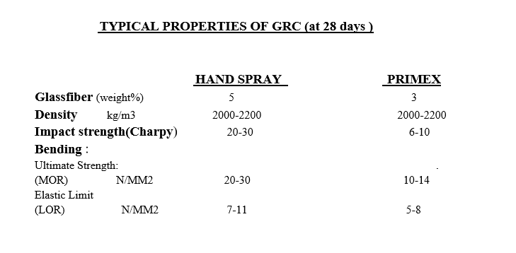
Sprayed GRC is generally stronger than premix vibration cast GRC, it achieves a fiber content of 5%, whereas premix GRC is limited to around 3%.
MIX DESGIN FOR GRC
Sprayed GRC Premix GRC
Sand 50kg 50kg
Cement 50kg 50kg
Water 16-17 liters 18-20liters
Polymer Optional Optional
Fiber glass 3-5%by weight 2-3% by weight
In general, using fiber lengths. 25-50mm. 12-25mm.
Plasticizer: Dependent on type of plasticizer and manufacture instructions
Sprayed GRC Manufacturing Procedure
A: In the spray-up process ,the water and admixture(and polymer if used) are placed in a “high shear mixer “and the sand/cement are slowly added until a smooth creamy slurry is achieved Mixing time is about 1 -2 minutes.
B: When ready the mix is transferred to a “pump/spray unit”. The pump conveys the slurry at regulated rate of flow to spray gun.
C: At the spray gun a continuous strand of glass fiber is fed into the compressed air powered gun, where the strand is chopped into predetermined lengths and combined with a sand and cement slurry.
D: The operator holds the spray head in his hand and moves it back and forth across the mould a thin, about (1.5-2 mm.) slurry or mist coat, without reinforcing, will normally be sprayed first to provide cover for the glass fiber on the finished surface, directing the stream of material perpendicular to the mould surface, until the required thickness of GRC has been built up.
Roller compaction ensures compliance with the mould face, impregnation of the fiber by the slurry, removal of trapped air and development of adequate density.
The rolled surface may be finally troweled smooth.
Thickness control is achieved by use of pin-gauges.
A typical output of a single hand unit is 10-12 kg of GRC per minute.
The process results in one surface of the product having an ex-mould finish and the other surface a rolled or troweled finish.
Premixed GRC Manufacturing Method
All premix processes involve the blending together of the cement, sand, water, admixtures and chopped strands of AR glass fiber in a mixer prior to being formed.
DEMOULDING: Release agent can be applied to cover the all inside surface of the mould, by spray or by impregnated sponges/cloths.
Remove any excess GRC which may interfere with demolding.
A steady force is quicker and more effective than hammering the mould.
GRFC CURING
Initial Cure: The completed panel in the form should be kept covered with polythene overnight (12-24 hours) to avoid drying and to achieve adequate strength for stripping.
Controlled Curing: After initial overnight curing, the product is removed from the form and placed in a curing environment not only to affect strength gain, but improper curing can cause warpage due to variations in moisture content and affect surface appearance (porosity, staining, efflorescence).
Panels must appropriately supported to a void curing marks or staining.
Correct panel support during storage also minimizes warping or bowing.
GRC Production Quality Control
The quality of GRC produced by manual spray is dependent on operator skill.
Quality control program must include control tests of materials.
GRC element should be marked with the date manufactured and an identification number referenced to production and erection drawings and testing records.
Test Procedures:
Production Testing (wet):
A-Determination of Slump Value of Cement Slurry (The Slump Test indicates whether a slurry is suitable for spraying).
B-Determination of Glass Fiber Roving Chopping Rate (Choppe Output Rate (The Bag Test).
C- Determination of Slurry flow rate (bucket test)
D- Determination of Glass Fiber Content (The Wash-Out Test).
E- Thickness should be checked frequently at a large number of places on the panel surface during each panel spray up.
Thickness of GRC Skin :
Hand spray 8mm – 5mm
Premix 10mm – 100mm
Production Testing (After Curing)
A- Flexural Testing
B-Determination of Bulk Density.
C-Shear Testing.
TOLERANCES:
Allowable Tolerances of Manufacture units
a) Overall Height and Width of units measured at the face adjacent to the form:
300 cm. or under ±.3mm
300-600 cm ± 3mm. – ± 5mm.
Each addition 300mm. ±3mm.
b) Thickness: Skin thickness +3mm
Allowable Tolerances of Erected units
a) Overall Height and Width face of joint
Panel dimension 300 cm. or less ±4,6 mm
Panel dimension 300-600 cm. ± 4.6mm-±6mm.
Each addition 300mm. ±3mm
b) Warpage: of one corner out of plane of the other +3mm
c)Bowing: Not over L/360, where L is the panel length.
G.R.C Panel Loading and Delivery
G.R.C products are usually transported on tractors and semitrailers, but rail or barge transportation over much greater distance is feasible.
The normal highway restrictions on weight and size will have to be observed because of their thin construction, which reduces weight, G.R.C panels can offer a significant cost savings in delivery.
Panel configurations should be developed that will permit nesting of the pieces for maximum truck loads.
If the pieces are nested or stacked vertically, consideration must be given to proper transfer of vertical load to prevent progressive crushing.
Once the job is ready to receive the panels, the loading sequence should be the reverse of the erection sequence.
This permits installation directly from the trailer and reduces costly double handling and jobsite storage.
Careful planning will ensure installation efficiency and minimize damage potential as result of excessive handling.
Appropriate soft materials to protect panels edges during shipmen are high density polymer, polystyrene, and elastomeric materials.
Since the trailer bed is flexible, two point support is most desirable.
The need for protective covering against road stains and weather has to be evaluated against its cost and effectiveness enroute.
Nylon straps should be used to tie down the load.
Special attention is required to protect the panels at the binding points of the straps, and to protect against the “slap” along reach of strap.
Care should be taken to avoid over tightening of straps which might cause panels deformations.
Site condition should allow erection equipment and transportation units to proceed under their own power to allocation where G.R.C panels can be handled by the erection equipment directly from the transportation units.
If onsite storage is an absolute necessity to enable the erector to operate at the speed required to meet the established schedule, storage areas provided by the general contractor / construction manager should by relatively level and firm, well-drained, and located where there is little chance of damage due to other construction activity.
If a loaded trailer is dropped at the jobsite, the shipper should carefully block the trailer to prevent accidental overturning, this is especially true on sites which are frozen, and subject to thawing, the dropped trailer should be parked on firm level ground.
Panels should be lifted slowly from the transport vehicle. If any binding occurs, the unit should be lowered and the obstacle holding the unit to be removed.
Remaining adjacent panels on the trailer should be tied or blocked to prevent tipping.
The exterior unit should always be unloaded first from a stack to prevent chipping and scraping panels should not be slide out from the middle of a stack.
Whenever possible, on a load with many panels, balance of the trailer should be maintained by unloading alternate sides of the vehicle.
Onsite Installation of Glass Fiber Reinforced Concrete GFRC
1. Coordination
An efficient jobsite operation is the result of planning between the manufacture, trucker, erector, and the general contractor.
A check of jobsite access for all necessary equipment is essential, also checking of building frame tolerance supporting surfaces will reduce delay.
Manufacture needs a sequence that will best utilize the available trucking equipment.
The erector needs a steady supply of panels to ensure efficiency and jobsite progress.
GRC elements must be erected on flat surfaces after the finishing of final plastering, to assure correct adjustment.
Fixation by using anchor bolts must be 50 mm at least from the edges.
Erection of GRC elements is prior to aluminum or glass works.
Erection:
Erection supervision requires knowledge about handling and positioning panels on the building.
Advance planning will ensure the presence of all necessary tools, equipment and loose connection hardware.
Jobsites condition must properly accommodate the erector’s equipment operating under its own power.
There is no substitute for advance field layout work to ensure horizontal and vertical control as the panels are positioned.
In general, panels should move directly from truck to building to minimize the hazards and costs of extra handling.
Should jobsite storage is necessary, the erector should observe proper yard storage practices.
The GRC erector should confer with the manufacturer on proper storage methods if they are not shown on the erection drawings.
The low weight of G.R.C panels permits lighter and less expensive handling equipment, therefore a simple hoist, mounted on the roof, or a small crane may be sufficient.
Care is required during lifting since the lightweight G.R.C panels cannot resist wind as well as heavier concrete units.
The erector should understand the function and performance of each connection detail to ensure that panels are installed keeping in view the design concept.
Field modification to the steel stud frame or connection system should be made only with the approval of the engineer responsible for the design.
If connections require temporary support, such as shims, they must be removed as soon as possible so that connection system function in the manner intended.
Field welding at temperatures below 20F (- 7 C) should be avoided because of the possibility of fractured welds.
A satisfactory installation results if the erectors understands product manufacturing and erection tolerances coupled with permitted variation in building frame construction.
During GFRC panel installation, priority is given to aligning the exterior face of the panels because of esthetics, this may result in the interior stud face not being in a true plan.
GRC panel design usually prevents stud spacing therefore, recommended that, if the stud are to receive interior drywall or similar treatment, the interior finish should be mounted on shimmed transverse channels rather than directly to the stud.
Window frames should be attached directly to the head and still tracks of the steel stud frame (or a separate framing system).
The window load, both dead load and wind pressure, are supported by the stud frame and transferred through the frame to the panel connections attached to the structure.
Window frame is shimmed by the glazier to its proper location and then screw attached to the steel stud frame.
The only contact between the window frame and the G.R.C skin is the joint sealant, allowing the skin to move and preventing undue restraint of the skin.
G.R.C skin can be expected to expand and contract up to 1/8 in. per 10 ft. (3mm per 3 m) as a result of moisture and thermal effects.
If this is ignored, restraint due to improper installation of the window frame may result in excessive restraint of the G.R.C skin, thus creating a possible and G.R.C skin also keep the wall system weathertight.
Insulation, fire proofing, electrical and telephone conduits may be placed in the wall cavity created by the steel stud frame.
Insulation and other trade items are installed at the jobsite by other subcontractors.
Painting:
Paint applied to exterior surfaces should be of the breathing type, permeable to water vapor but impermeable to liquid water.
Painting of GRC works is prior to general façade paint ,to avoid mesh dirt.
Cleaning of GRC Panels
Many G.R.C panel projects will require only spot cleaning with soap and water in isolated areas while other projects may require a general cleaning.
More stubborn dirt may require a commercial cleaning compound or a dilute solution of muriatic acid.
The G.R.C surface should be wetted in advance to prevent deep absorption by strong cleaners.
A 3 to 5 percent phosphoric acid should may be more effective on white concrete and also helps to avoid a yellow stain.
When using acids, special care is required in masking and protecting adjacent materials to avoid damage.
GRC Patching and Repair
Since G.R.C panels are inherently resilient and ductile, light in weight and highly resistant to crack propagation, there should be few chips and spalls resulting from storage delivery, and handling.
However, a certain amount of repair of product is to be expected as a routine procedure.
Production blemishes should have been corrected at the plant.
Since patching and repair of GRC is a specialized activity, it is recommended that manufacturer representative should be consulted for GRC repair work because they understand the use of bonding agents and shading or texturing technique.
It may even be necessary to prepare a composite patching mix reinforced with glass fiber.
Damage that affects the structural capacity should be discussed with the design engineer.
In general, the extent of patching and repairing required should be minor.
Joint Sealing
Architectural considerations and tolerance realities usually require the use of one stage or two stage joints using elastomeric sealants, one stage joints are most commonly used in the united states, normally in the form of a sealant close to the exterior surface.
A minimum G.R.C panel return of ½ in. (38 mm) at the joints it’s recommended with 2 in. (51mm) preferred.
The joints of an installed project should be inspected for satisfactory tolerance and freedom from dust and contaminants.
If a primer is recommended by the sealant manufacture, special care should be exercised to avoid staining the outside face of the panel.
The recommended backup rod of appropriate size should be set at the correct depth of joint.
When inserting a polyethylene foam backup rod a blunt tool should be used to avoid skin puncture of the rod and possible out gassing which may cause blistering of the sealant.
All recommendation of the sealant manufacturer should be carefully followed.
REFERENCE STANDARDS AND SPECIFICATIONS:
British Standards Institution: BS 6432:1984 British Standard Methods for Determining Properties of Glass Fiber Reinforced Cement Material.
Glass Reinforced Cement Association (GRCA):
GRCA S0105 Specification for Alkali Resistant Glass fibre for Reinforcement of Cement and Concretes
GRCA S0110 Specification for the Manufacture of Glass fibre Reinforced Cement (GRC).
GRCA S 0106 Guide to Specification for Glassfibre Reinforced Cement Cladding.
American Society for Testing and Materials (ASTM): ASTM-C947-89 Standard Test Method for Flexural Properties of Thin SECTION Glass Fiber Reinforced Concrete.