This method statement covers the construction of quay wall identified on the project drawings as per the employer’s requirements, with cope at 3.35 m CD, having a design depth of -12.5m CD including foundation works and anti scour protection below -12.5m CD level, tying-in with the existing quay walls and complete with navigation, berthing and mooring equipment and provision of spare berthing equipment.
The scope of the work required includes the following:
Construction of a new quay wall comprising:
A new quay wall identified on the drawings.
Dredging to lower the seabed in front of the quay wall to –12.5m CD and disposal of spoil to a location to be agreed with the Employer.
Removal of an existing pipe spooling jetty, piles along shoreline, small craft quay and disposal of materials off site.
Such temporary works as may be required to maintain the integrity of the existing quay walls, edge of container yard, outfall channels and any other structures earthworks during construction for the new quay wall.
Backfilling behind the quay wall using dredged sand material provided by the Contractor. The Contractor shall be responsible to determine where sand material can be obtained for the backfilling and shall obtain the necessary approvals from the relevant authorities for the removal of sand. Backfilling shall follow the removal of slope protection material including piles and concrete blocks along the shoreline close to the Contractor`s construction yard. The slope protection rock material may be used in the works if suitable or elsewhere at a price agreed with client. This will be deducted from the Contractors payment claims.
A paved quay apron 30 m wide behind the new quay wall and the ends of the existing walls.
Pipe trenches in the quay wall and apron.
Surface water drainage installations including extensions of 3no. existing outfall culverts and incorporation of 2no. into the new quay wall extension.
Supply and installation of replacement fenders and repair of concrete along the existing quay wall.
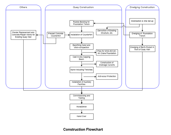
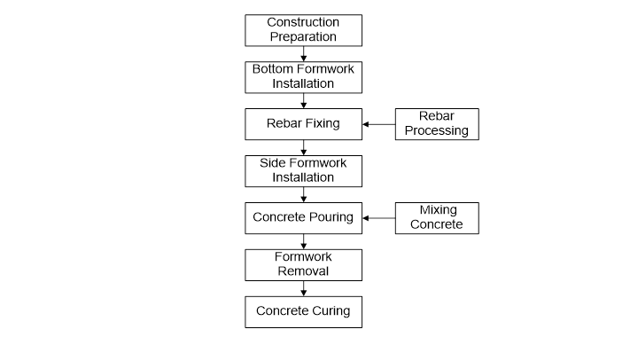
General Construction Flowchart
To ensure the achievement of schedule of the project, the construction of each phase/section should be started as early as possible.
As the dredging of foundation trench gets started, the construction of precast concrete counterforts should be initially performed, so as to proceed the following construction as soon as possible.
The general construction flowchart of the Project is shown as follows:
Construction Sequence
On receiving the necessary approvals the manpower mobilization will be started immediately.
Most of the manpower will be mobilized, so that the Project can be started as soon as possible.
Normally, the senior staffs will be initially mobilized to the site within four week to start the preparation works.
Part of skilled workers will be mobilized initially to start the construction of temporary facilities within three month.
Other skilled labors and semi labors will be mobilized subsequently basing on the construction schedule.
Part of skilled workers, semi labors and unskilled labors will be recruited locally.
The mobilization of the Equipment, such as grab dredger, flat top barge, floating crane, etc., will also be commenced early.
After obtaining the construction permission and consents, the dredging construction will be executed immediately.
Dredging Procedure
The works comprises the execution of dredging works required for foundation trench and leveling of the berth pocket in front of the new quay wall to -12.5 m CD as indicated on the drawings in Employer’s Requirements.
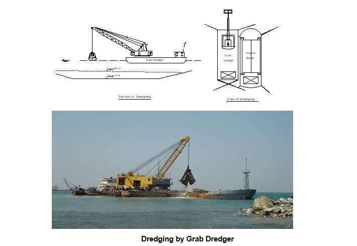
Grab dredger will be allocated to the dredging works with the assistance of the split hopper barge.
All dredging work will be carried out vertically in layers and horizontally bays.
The sketch of dredging construction by grab dredger is shown as below:
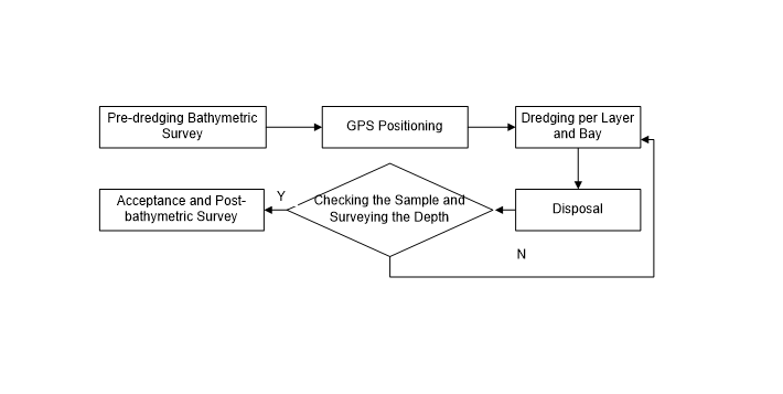
The procedure for dredging construction is shown as below:
The dredger will be positioned by GPS system.
During the dredging, the level of dredging will be measured by lead.
One hydrographic measuring station will be also set on the existing quay.
The dredging sample will be checked and compared with borehole data in time when it is carried out to each layer.
The width and depth of the dredging area will be controlled in a tolerance of Employer’s Requirement.
If the sample is different with the design, it should be reported to the Employer to make further decision.
Significant data and information of the dredging will be recorded.
The dredging works will be monitored by regular hydrographic progress survey in order to verify that works are being executed in accordance with the scope of design.
The survey will be carried by echo sounder and GPS positioning device.
The post-dredging survey must be carried out immediately after the dredging of the bay is finished.
Construction Sequence and Schedule
The dredging sequence will be executed from dredging of foundation trench to dredging of berth pocket in front of quay wall.
Considering the site condition, disposal distance and vessels’ maintenance, about 1,200m3 materials per day will be executed by grab dredger.
Disposal of Dredging Materials
The disposal areas are not yet identified exactly but it is assumed that dredged materials will be dumped offshore to a location to be agreed with the Employer.
Dredging Equipment
Major intended equipment resources for dredging are listed as below:
| S/N | Description | Qty. | Remark |
| 1 | Grab Dredger, 13m3 | 1 | |
| 2 | Split Hopper Barge, 500m3 | 2 | |
| 3 | Tug Boat, 1000Hp | 1 | |
| 4 | Traffic Boat | 1 | |
| 5 | GPS Positioning Device | 1 | |
| 6 | Echo Sounder | 1 |
Rubble Bedding for Foundation Trench
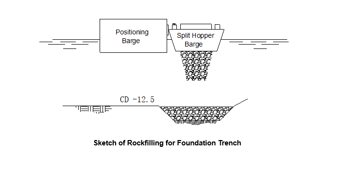
Rockfilling
The sketch of rockfilling for foundation trench is shown as follows and the rockfilling quantity is about —– m³.
Stones will be supplied from the land and transported to the temporary quay.
The excavator will be used to load the stones onto the 15m3 hoppers.
When hoppers are fully loaded, they will be transported to the specified position for rockfilling.
For accurate positioning for hoppers, flat top barge will be used for positioning by GPS.
The method of plumbing will be adopted to control the rockfilling height accurately.
Before the rockfilling starts, the foundation trench, which has been accepted but is not yet covered with rockfilling, shall be surveyed again.
If the thickness of back silting is above specified profile, it shall be reported to the site Engineer, and the work for clearance of silt shall be organized.
Trial rockfilling shall be performed prior to determine the location of the hopper and thickness of stone dumped at a time.
Through different trial rockfilling with different loads of stone, the load for a certain rockfilling thickness can be determined.
Thereby, proper methods for loading and positioning can also be acquired.
First, the hopper will be used for the coarse-rockfilling, and then the flat top barge loaded with stone will be accurately positioned for supplementary rockfilling.
During the rockfilling process, frequent plumbing and mark aiming will be performed to avoid under-rockfilling or over-rockfilling.
Settlement shall be taken into consideration for the rockfilling of foundation bed.
The preserved amount of settlement shall be determined by design requirement.
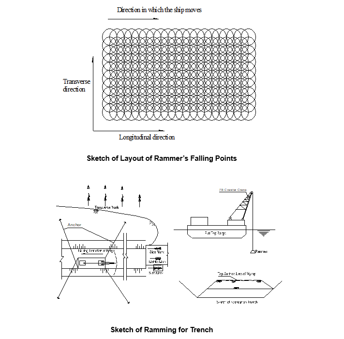
Ramming Method
One crawler crane 70t will be fixed on the flat top barge for foundation trench compaction.
The foundation trench shall be compacted by ramming in layers according to thickness; and the thickness of the layer is not advisable to be greater than 3m after compaction.
Adjacent ramming rounds with half overlapped with each other longitudinally and transversely will be adopted for compaction.
The rammer will be planned to use 5t in weight with 1.0m diameter circular bottom.
When the buoyant force and resistance is not taken into account, the impact energy of each ramming is not advisable to be less than 120KJ/m2.
The compact energy can be obtained when lifted height is up to 2.5m.
Rammer shall be lifted up to 3 m to achieve compact energy of 130kJ/m2 for each ramming.
The ramming for rockfilling bed shall proceed from one point to another, with adjacent ramming circles half overlapped with each other longitudinally and transversely as shown in the sketch, and will be carried out in two rounds, with the initial ramming followed by the recurrence, four times ramming at each point for each round, and 8 times ramming in total for each point.
Foundation trench shall be divided into 2 sections, with 2 m overlapped length, and 3m in thickness for each layer.
The plane of each rockfilling layer shall be checked before starting the ramming, and leveling shall be executed if height difference between adjacent locations is more than 0.3m.
Typical area, with 1m exceeding each side of counterfort and length of 10m, shall be chose as the trial section.
Initial ramming and recurrence will be executed by the same means of adjacent ramming rounds half overlapped with each other longitudinally and transversely to prevent local heave of foundation bed or flaw of ramming. 1 m exceeding front/back side line of the counterfort will be taken for rammed width.
The reserved settlement value will be adjusted according to the trial ramming properly.
Leveling
The area of foundation trench to be leveled is about 6700m². When the rockfilling for foundation trench is completed and accepted, the work of leveling will be commenced at once.
Survey rod will be controlled by the total station for rails placement of the leveling work, while the survey rod will be controlled by the water level to obtain the elevations.
For the placement of rails, the control points shall be set on the temporary survey station.
Please refer to the following sketch for leveling of foundation trench:
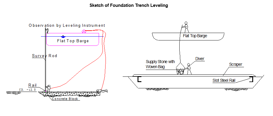
One leveling barge and some divers will be involved for foundation leveling.
The amount of rubble stone and crushed stone shall be estimated beforehand according to the as built section of the rockfilling works, and the stone needed shall be prepared.
Flat top barge will be served for leveling, which can be loaded with the stone for leveling.
Crushed stone will be used at the last step for fine leveling, via the woven bag which will be raised and put down by manpower, the crushed stone will be transited to the location controlled by the diver for leveling.
Divers will be employed to lay the steel rails underwater, and a leveler will be equipped on the rails to level the crushed stone within reach.
Surveyors shall erect the total station at the survey station and direct the divers to place the steel rails by observing the instruments.
The divers shall place concrete blocks underwater to support the steel rails.
Elevation of the rails shall be controlled by the water level and survey rod.
When the steel rails are ready, two teams of divers shall dive into water at the same time, and push the leveler forward along the steel rails.
During the process for fine leveling, rubble stone shall be used to fill the uneven position among rock blocks, while crushed stone shall be used to fill the uneven position among rubble stone.
The crushed stone is allowed to form a layer with thickness less than 5cm.
Only those crushed stone of 2~4cm shall be used, via the bamboo basket which will be raised and put down by manpower, the crushed stone will be transferred to the position required through underwater wire telephone communication between the diver and surveyor.
The divers shall push the leveler (such straight hard material as channel steel) along the rails to level the stone, and the completion of leveling for a section of foundation bed shall be followed by the operation for the next section.
Elevation and position of rails shall be rechecked at the time after the fine leveling. If any deviation beyond allowable is found, the rails shall be adjusted.
Life buoys connected with concrete block through nylon rope shall be placed for each corner of the leveled section of foundation bed, and those area completely leveled shall be kept away from anchoring of vessels.
Precast Counterfort units Procedure
There are — units of counterfort (CF) to be precast in this project, with —- units of standard and — special.
All of the CFs will be prefabricated at the precast yard, with —— m3 concrete involved.
The precast sequence will be in accordance with the requirement of site installation.
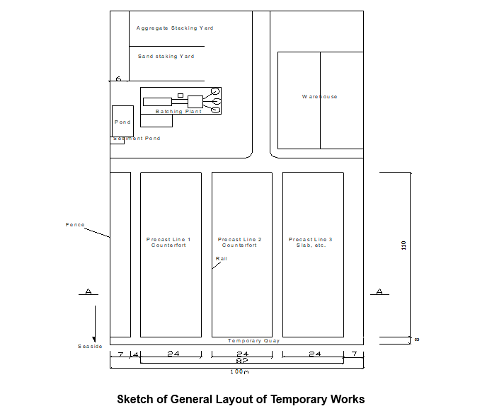
Existing Temporary Works
Existing temporary works, including precast yard, batching plant, etc., will be used after decoration and repairs.
The sketch layout of temporary works is shown as following:
Precast Counterfort Construction Method
General arrangements:
Two precast lines will be arranged for CF prefabrication.
8 CF units will be completed every month.
Ballonet method will be used for transporting the precast unit.
Bottom Formwork Preparation
For the convenience of ballonet loading out, 5 groups of I-Steels (32#) and one group channel steel shall be placed transversally on the floor to form 5 interspaces, at the ends of the interspaces, built-up type steel formwork shall be placed transversally to connect with the longitudinal I-bars.
Thus the outline of the bottom formwork can be formed.
Sand shall then be filled into the 5 interspaces, which shall later be watered and compacted until the surface of sand is the same level as that of the I-bars and channel steel.
Afterwards, 20mm thick wooden board and paper shall be placed onto the sand form the bottom formwork.
To transport the components, remove the transversal steel formwork at the ends of the I-bars, clear away the sand in the interspaces, then insert the ballonets into the interspaces, when the component is lifted by the ballonets filled with air, the I-bars shall then be removed, and the component can be loaded out to the temporary quay by revolving the ballonets in shift.
As there 2 special counterfort in this project, one set of the formworks should be changed correspondingly.
These special will be planed to be produced finally, so that the formwork will not have to be changed for tow times.
Processing and Erecting of Rebar
After processing in the shed, the rebar shall be transported to the site by trucks and then be erected on the bottom formwork.
Auxiliary steel frame for rebar erection between rib slab and the upright slab shall consist of 7 layers, each layer 2.0m in height.
The auxiliary framework mentioned shall be welded into an integer by profile steel and fixed with the bottom formwork.
Erecting of rebar shall be kept stable and fasten.
In order to hang the vertical rebar of upright slab and rib slab, movable profile steel and horizontal hanger rod shall be set up on top of the steel framework.
Vertical rebar shall be hanged onto the horizontal hanger rob according to the design space, a certain numbers of horizontal rebar shall be fastened on the top, middle and bottom of the vertical rebar to form a frame structure, afterwards, from the upper to the down.
The inner rebar shall be erected first, then the outer horizontal rebar, and finally the rebar for bottom slab.
When the bar erection work is completed, concrete cover spacer shall be placed on the surface of the rebar cage, outer formwork can be installed then.
Supported by the outer formwork, the rebar of the counterfort shall keep stable, afterwards, the frame for bar erection will be hoisted out, and the working procedure for fixing and erection of rebar has been fully finished.
Side Formwork
The gantry crane 20t will be used for formwork installation/ removal, while the inner formwork shall be installed layer by layer, concrete casting shall be performed continuously until it is completed, so that the concreting can go on smoothly, and the quality of the counterfort units can be well ensured.
Formwork for one side of bottom slab shall be installed as a whole according to the setting-out location.
Large formwork with a weight of 15t will be used as outer formwork.
Outside the steel plate surface, horizontal trusses shall be erected at the height of 1.2m.
The adjacent trusses at both ends of the upright wall of counterfort will be connected into a whole to form a bearing grid.
Bolts that can be fastened at both ends will be equipped in each rib of the horizontal trusses of the upright wall.
Therefore, a bearing structure of multi-span continuous beam is formed.
The bolts that can be fastened at both ends shall then be connected with the frame of inner formwork.
Both the counterfort rib slabs and the inner formwork of the upright wall consist of 7 layers with 2m layer height.
Position for erecting of formwork shall be set out on the bottom formwork, and the marks shall be made at the place where supporting concrete block need to place.
Place concrete column block at the right place, where steel formwork for bottom slab shall be installed.
The inner formwork for each layer shall be hanged to the corresponding steel truss, and removable formwork chamfered for the convenience of formwork removal shall be installed at the corner.
Bolts shall be installed between inner formwork and outer formwork.
The support column for inner formwork of each layer shall be connected by bolts end to end, and sealing strip shall be used for joints between formwork.
A platform with bevel will be erected with the inner formwork to facilitate the concrete casting.
The weight for each section of inner formwork and the support frame is about 10t, and it will be hoisted and installed by gantry crane.
As there are 2 special counterfort is this project, one set of the formworks should be changed correspondingly. These special ones will be produced last, so that the formwork won’t have to be changed two times.
Concrete Casting for Counterfort Units
With reference to the design of formwork, the outer formwork installation shall be completed at the beginning for concrete casting.
The inner formwork between two ribs shall be divided into 7 layers.
They shall be assembled section after section, and then be installed layer by layer along with the concrete casting process.
When the installation of formwork is completed and concreting has been approved by the Engineer, the concrete casting may be commenced at once.
The gantry crane with the concrete bucket or concrete pump truck will be used for the casting operation.
Concrete will be supplied by the batching plant on site, and be delivered to site by concrete truck.
Later, the concrete will be released into the concrete bucket, hoisted to the formwork by the gantry crane or directly cast by pump truck.
Labors shall then be employed to release the concrete into the formwork and compact it by the internal vibrator.
The bottom slab and the first layer of 2m high wall and rib shall be cast first, and then the inner formwork for each layer shall be installed along with the increasing concrete.
Each layer for concrete casting shall be 2m in height. About 2 hours (less time for the smaller upper section) will be taken for the casting of each layer. About 1 hour for formwork installation of one layer. So 3 hours will be taken on average for completion of one layer.
Taken other factors into consideration, the 7 layers including the bottom slab, can be completed within 21 hours.
Meanwhile retarder shall be added into the concrete to ensure the initial setting time prolonged to 4.5-5 hours.
In the case of heavy rain during casting concrete, the casting can make a pause temporary, and be better to cover the concrete with plastic sheet for a while.
If the casting cannot be stopped or resumed after pausing, the mix of the concrete should be adjusted appropriately.
Curing
When the required strength of the concrete is obtained and approved by the Engineer, side formwork can be removed.
The concrete shall then be marked and be cured continuously with fresh water.
Water for concrete curing shall comply with the design requirement.
The unit shall be cured with water for 7 days.
When the component reaches the 100% of the design strength, it can be moved to the temporary quay by ballonets, and then be hoisted to the barge for installation by barge crane.
Installation of Counterfort Units
There are —- pieces counterfort (CF) units weigh about —- ton for each. They will be transported from the precast area to the temporary quay by ballonets, loaded on flat top barge 1000t and installed by floating crane with maximal hoisting capability of 800t.
Construction Method
Ballonet will be used to transport the CF from precast area to temporary quay for installation.
Structure of ballonet is shown as follows:
A ballonet consists of its body, head and nozzle, etc.
Its auxiliary parts include safety valve, pressure meter and pipe joints, referring to the following sketch:
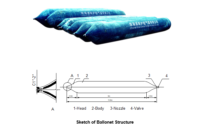
The ballonet to be used in this project is made up of 6 layers. The allowable working pressure is 0.2MPa; and the extreme pressure is 0.5MPa.
One piece of φ1000mm*9m ballonet weighs about 250kg; and generally the mass of the air charged can be omitted.
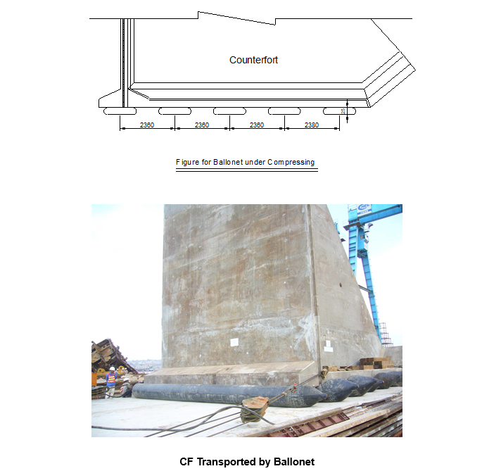
In order to ensure horizontal load for the CF at the beginning of lifting up the unit, the ballonets shall be set regularly along the moving direction of the CF.
As per the level load principle:
Leveling for foundation trench rockfill must be inspected and accepted before installation.
The CF units will be hoisted and loaded on barge in sequence after the concrete compressive strength of the units reach the designed strength.
CF units will be hoisted about 50cm above the ground at first, and it will be lifted up again when the floating crane becomes steady.
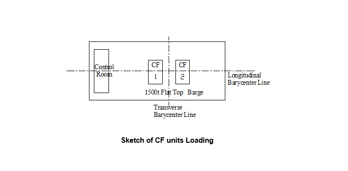
Barycenter lines of the CF unit and 2000t barge must be matched together when loading the unit on the barge in order to avoid inclination of the barge caused by imbalanced load.
The plan for CF units loading on barge is shown as below:
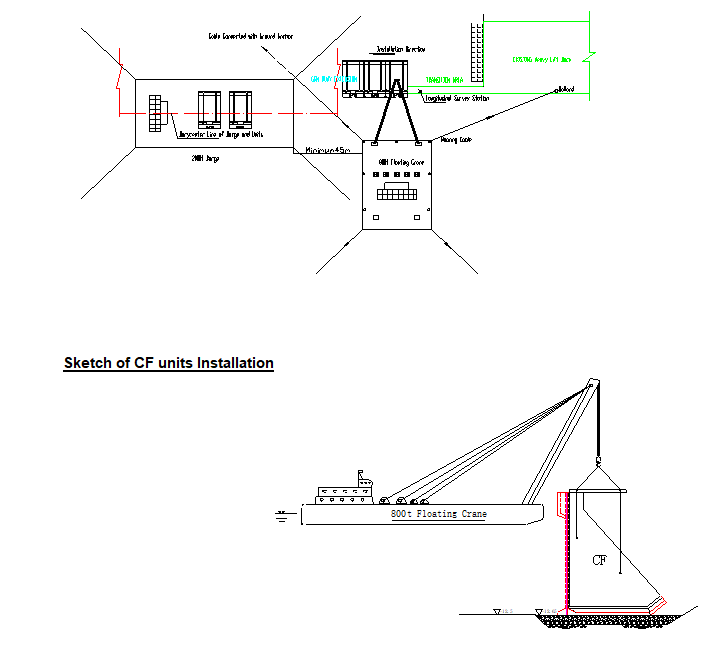
The floating crane and flat top barge will be moved to the Quay site with the help of tug boat.
Bow direction of floating crane shall be normal to the cope line of the quay, and two front anchors will be connected with ground anchors buried onshore or bollard.
Survey stations shall be prepared before installation.
The survey stations should be ensured observation without obstruction during installation, longitudinal survey station and GPS shall be prepared separately for controlling the positioning.
Installation sequence will commence from the Heavy Lift Dock to existing Quay. Timber will be prepared to control joints width in advance.
The positioning for floating crane and survey controlling are shown in the sketches.
CF unit can be put on the foundation trench when the positioning is satisfied, and divers will check width of joint and staggering between neighboring units separately.
The shackles can be released and removed when the checked items are qualified.
Observation points for settlement and displacement can be set after the installation, and they will be surveyed regularly or irregularly according to the requirement.
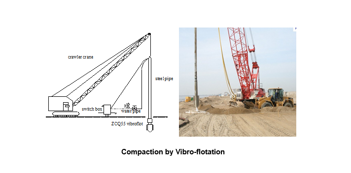
Backfilling Sand and Vibro-compaction
Backfilling Sand
Backfilling sand will be executed after the completion of geotextile filter layer. Dredged sand will be used as backfill material. The quantity of the backfilling sand behind the quay wall is about 590,000m3.
To prevent the foundation being silted, the sand will be backfilled when 30 CF units (about 255m) are installed, and the method of backfilling is hydraulic backfilling.
The bathymetric survey should be carried out by GPS echo sounder or hand-lead survey before backfilling, and then topographic map will be made to calculate the quantity for hydraulic backfilling.
Hydraulic backfilling shall be executed by reclamation dredger and be assisted to fill by bulldozer, dumpers and excavator.
Meanwhile the settlement and displacement of CF units will be monitored by surveyor during backfilling.
The diver will check the geotextile filter layer to ensure its stability during construction.
Backfilling will be executed with the sequence of CF installation.
The outlet of the hydraulic backfilling pipe will be laid in the location which is about 40m from the copy line.
Dredged sand will be used as the material, and backfilled sand will be transported, loaded and leveled by excavator and bulldozer to the front, Manpower will be used for partially trimming.
The Level of the quay apron after backfilling between 3 and 30m from the cope line is about +3.0m, so the level after vibroflotation is about +2.0m, which is above water level and is convenient for the subsequence construction, and the level of the remainder is about +3.5m which should comply with the Employer requirement.
Vibro Compaction
The backfilled sand will be treated (vibro-compacted) which is between 3m and 30m from the cope line.
Vibro-flotation lifted by crawler crane will be allocated to carry out this construction, referring to the following sketch:
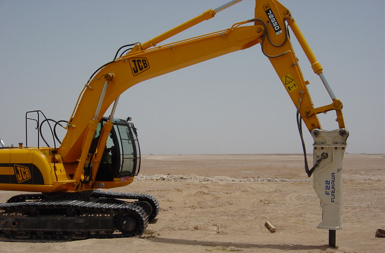
Demolition Works
The existing pipe spooling jetty, piles along shoreline, slope protection material and emergency small craft quay shall be demolished and removed from site, specified in Employer’s Requirements.
Hydraulic breaker and excavator will be mainly used for the demolition works.
If agreed with the Engineer, the piles may be cut off at sea bed level, provided they do not interfere with the quay wall works.
Acceptance of demolition works will be granted following the acceptance of the surface by the Engineer and receipt of all required documentation.
The disposal areas are not yet identified exactly but it is assumed that demolition materials will be dumped offsite at a distance, in a legal manner and with the approval of local Authorities.
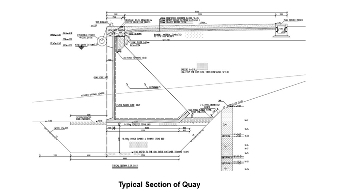
Cast In-situ Capping Beam
There is 442.9m cast-in-situ capping beam for the quay wall, which is divided into 26 segments. The design compressive strength of the concrete is 40 MPa, and the quantity of concrete involved is about 2861m³. The standard section of quay wall is shown as below:
Take the entire segment divided in accordance with the design as a construction unit (17m as a segment), concrete will be cast in place every other segment from Heavy Lift Dock to GRN Quay, and concrete casting for each segment shall be finished at a time.
The flow chart of cast in-situ process is as follows:
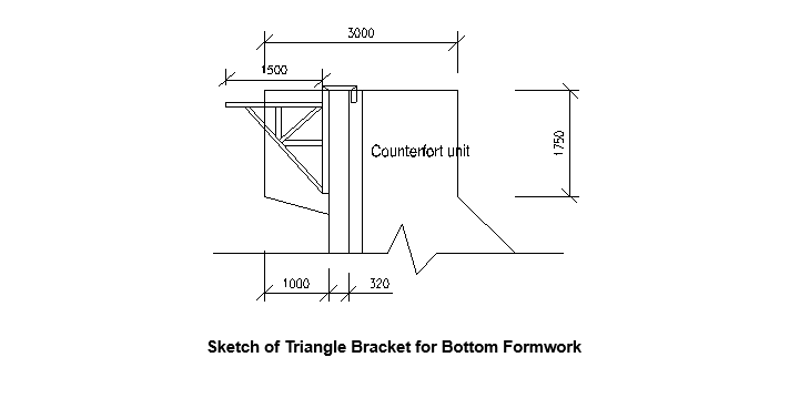
Triangle bracket will be installed at first; and then 100*100mm timber and plywood for bottom formwork.
Side formwork structure shall be 8mm thick steel plate integrated with enclosing purlins.
Formwork includes outside part, inner part, and end-sealing part. Side formwork will be installed after the rebar erection is inspected and accepted by the Engineer.
Side formwork will be installed by crawler crane, and the shape, straightness, and dimension of the formwork shall conform to stipulations set forth in relevant codes.
The embedded bolts such as the rubber fender’s, bollard’s and ladder’s should be fixed accurately and firmly at the same time.
Concrete will be produced by batching plant on site; it will be transported to the quay wall site by mixer truck and will be cast by concrete pump.
Internal vibrator will be used for compacting concrete.
Vibration quality shall be ensured during casting, defects as honeycomb on concrete surface and air voids should be avoided.
Finishing shall be performed with trowel when top elevation reaches, and screed by manpower shall be used for leveling before initial setting of concrete.
When concrete compressive strength reaches 10N/mm2, side formwork can be removed according to BS 8110 part 1.
Side formwork will be removed by labors with the help of crane.
Attentions to safety and integrality of formwork should be paid during the removal of formwork, don not prize and hammer here and there so as to avoid deformation of formwork.
Bottom formwork will be removed at last when compressive strength conforms to relevant stipulation.
The structure shall be covered immediately and cured with fresh water or by applying curing agent, and moist curing period shall not be less than 7 days.
Drainage Culvert
Surface water drainage installations, including extensions of 3 no. existing outfall culverts and incorporation of 2 no. into the new quay wall extension, will be cast on site.
The concrete will be provided by the batching plant.
Construction of Apron including Trench
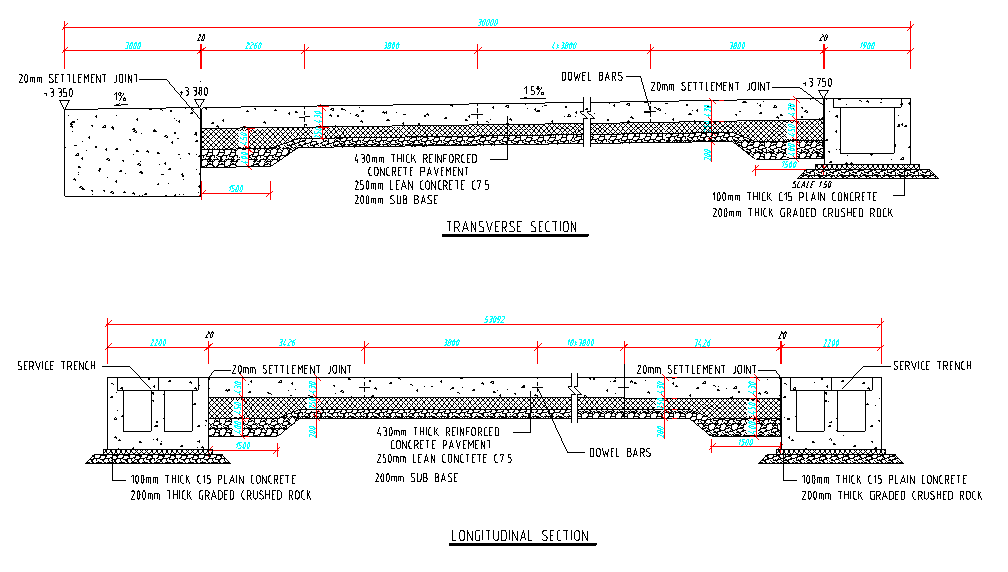
The quay has an apron of 30m wide. The section covers capping beam and concrete pavement (service trench).
As for the 25.1m wide pavement, it consists of a 200mm thick graded crushed rock sub-base, a 250 thick lean concrete C15 base course and a 430mm thick reinforced concrete C40 surface course.
The total thickness is 880mm, and the section of apron is as follows:
Service Trench
Service trenches are situated longitudinally and transversely in the quay.
The dimension of the trench situated transversely is 1.87m in height and 2.2m in width, it is a single box with two cells.
Dimension of the longitudinal trench is 1.65~1.87m in height and 1.9m in width, which is a single box with one cell.
Cover slabs will be precast and installed for the trenches.
The compressive strength of the concrete for the trench is 40MPa. There is about —- m3 concrete involved in service trenches.
Cover slab prefabrication is prior to the principle part of trench construction.
The trench construction procedure is as follows:
- Foundation excavation
- graded crushed rock sub-base
- C15 lean concrete base course
- rebar assembling
- side formwork installing
- concreting
- curing
- cover slab installing
Steel side formwork will be used for service trench, which will be installed and removed with the help of the crawler crane.
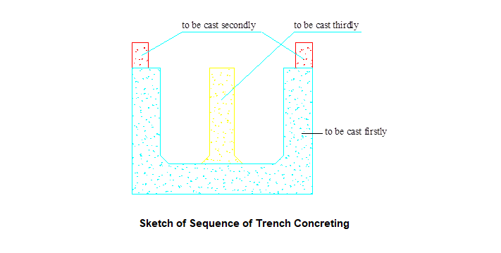
Concrete placing shall be divided into three times. Firstly, concrete of bottom slab and side walls is to be cast; secondly, the pedestal for cover slabs is to be cast to ensure its straightness; the central partition (only transverse trench) is to be cast finally.
The casting sequence is shown as below:
After side formwork removal, concrete shall be cured timely in accordance with relevant requirements, and it shall be kept damp not less than 7 days.
Qualified Cover slab will be installed by 65t auto crane after the pavement is finished.
Sub-base
200mm thick graded crushed rock which lies on backfilled sand sub-grade after compaction will serve as unbound sub-base for pavement; and 3084m3 graded crushed rock will be involved in sub-base.
Construction for sub-base will be executed form west to east in section and in one layer. And the procedure is as follows:
Prepare → graded crushed rock spreading → compacting
When the compactness of sub-grade has been accepted, setting out for graded crushed rock sub-base can be executed, whilst graded crushed rock can be stored and tested in accordance with design requirement or relevant codes.
Type SD23 bulldozer will be used for spreading for crushed rock; and partial trimming and leveling shall be executed by manpower to ensure thickness and level of the sub-base.
Compaction should be carried out as soon as possible after crushed rock has been spread according to the requirements and relevant codes.
Type LSS218B vibratory roller with static linear load 415N/cm will be used for compaction. Basing on the design thickness of the sub-base is 200mm, 7 passes will be executed for compaction in accordance with requirement.
Special care should be taken to obtain full compaction in the vicinity of both longitudinal and transverse joints.
A minimum width of 2m of properly compacted sub-base beyond the edge of the lean concrete should be prepared before actually placing the lean concrete.
Base Course
250mm thick lean concrete C15 which lies on the sub-base will serve as base course for pavement; and the quantity of lean concrete is about 3855m3.
The construction sequence for lean concrete is stated as below:
Site prepare → formwork installation → concreting → curing
Setting out for lean concrete base can be executed after sub-base has been accepted.
Lean concrete will be constructed longitudinally in about 5m strips.
The staggered distance between longitudinal joints of lean concrete base and upper layer pavement slab shall be more than 300mm; whilst the staggered distance between transverse joints of lean concrete base and upper layer pavement slab shall be more than 1m.
Concrete for base will be produced by our batching plant, and the slump constant of lean concrete shall be met with the design requirement.
Lean concrete will be transported by mixer truck.
It shall be constructed in one layer and in strip along longitudinal direction of quay wall.
Hand guided method shall be adopted for concreting in a continuous process.
Internal vibrator will be used for compaction.
The side formwork shall be removed by labors.
Curing liquid or fresh water shall be involved in curing.
Lean concrete shall be cured in accordance with relevant requirements.
Surface Course
430mm thick reinforced concrete C40 which lies on the base course will serve as surface course for pavement, with the quantity of about 6631m3.
Construction for reinforced concrete will be executed transversely segment by segment; and every segment of the reinforced concrete slab, which is in accord with the design plan, will be cast in one layer.
Its procedure is as follows:
Prepare → rebar prepare and erection → formwork installation → concreting→ curing
When the lean concrete base has been accepted, setting out for reinforced concrete slab can be executed, whilst reinforcement cages can be prepared.
Steel side formwork with reserved holes for dowel bars will be used for reinforced slab.
Formwork will be installed when reinforcement cages for pavement slab have been finished.
Dowel bars shall be installed after formwork has been installed.
The concrete shall be produced by the batching plant in precast yard; it will be transported to the quay site by mixer truck and will be cast by concrete pump.
Internal vibrator will be used for compacting concrete.
Vibration quality shall be ensured during casting, defects as honeycomb and big air voids should be avoided.
Finishing shall be performed when top elevation reaches, and concrete finishing machine will be involved in leveling concrete surface.
Screed by manpower shall be used for leveling before initial setting of concrete.
Curing liquid will be sprayed when the concrete sets finally, and geotextile will be covered subsequently.
The damp curing will be applied at least 7 days.
Side formwork will be removed by labors when concrete compressive strength reaches 10N/mm2.
Then the contraction joint will be cut immediately after the removal of side formwork.
Installation of Auxiliary Facilities
Auxiliary facilities, including bollard, fender, ladder, etc. will be installed after the completion of capping beam and apron.
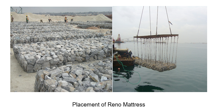
Placement of Anti-scour Protection
Reno mattress, L*W*H=3000*2000*500mm, is designed for anti-scour protection in front of quay wall.
The construction sequence is as follows:
Site preparation → Mattress assembling → Foundation preparation → Mattress installation.
Site Preparation
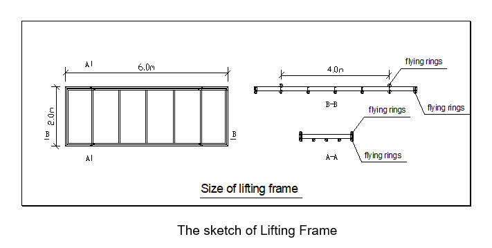
Mattresses, stone for mattresses and lifting frame should be prepared before construction.
The size of lifting frame is 6.0m in length and 2.0m in width the sketch is shown as follows:
Assembly and Filling
The folded units shall be taken out from the bundle and placed on a flat ground.
Mattresses should be opened, unfolded and pressed out to their original shape.
Front, back and end panels shall be lifted to a vertical position to form an open box shape.
End flaps shall be folded and overlapped, as appropriate.
All edges of the diaphragms and panels shall be tied or fastened to front and back of the mattress.
The mattresses should be assembled individually, by erecting the sides, ends and diaphragms, ensuring that all creases are in the correct position and the tops of all sides are level.
Then, the edges of the mattress will be connected by using lacing wire.
When using lacing wire, cut a sufficient length of wire and first loop and twist the lacing wire to the wire mesh.
Proceed with tying alternate double and single loops through every mesh opening approximately every 100 mm, and pull each loop tight and finally securing the end of the lacing wire to the wire mesh by looping or twisting.
The lacing wire should be supplied with the mattresses.
After being assembled, the mattresses shall be filled with rocks.
Rocks for mattresses shall be hard, angular to round, durable and of such quality that they shall not disintegrate on exposure to water or weathering during the life of the structure.
Care shall be taken when placing the stone to avoid damaging the wire coating.
After a layer of rock has been placed in the cell, sufficient hand manipulation of the rock shall be performed to minimize voids and achieve a maximum density of the rock in the units.
To allow for settlement, fill more and level it off above the tip of the mesh.
Then lay the lid down and pull the edges of the panels to be connected.
The lids shall be tightly laced along all edges, ends and diaphragms in the same manner as described for assembling.
Foundation preparation
The foundation on which the mattresses are to be placed shall be level to the elevations as shown on the project construction drawings and surface irregularities, loose material and vegetation in accordance with the project specifications.
Mattress Installation
Finally, the mattresses shall be placed in their proper location and securely attached to the adjacent ones.
In principle, the mattresses will be installed by the autocrane on the quay, and probably a few by crane on the barge.
Control for installation:
When installing the mattresses, direction of the installing mattress should be controlled by the following steps.
- First, before the mattress lifting underwater by crane with lifting frame, the location should be adjusted by pulling ropes and moving the crane hook above the water.
- Then, diver shall dive under water to adjust the location of the mattress by directing the crane until the location is right.
- Finally, take off the hooks and make a mark on the capping beam to record the installation location.