
The purpose of this Method Statement is to define the procedures, responsibilities, quality requirements, inspection criteria, testing requirements, and safety measures for the installation of the Lightning Protection System (LPS).
The objective is to ensure that the Lightning Protection System is installed safely and in accordance with approved shop drawings, project specifications, risk assessment reports, applicable international standards, local authority regulations, and manufacturer recommendations to provide effective protection against direct lightning strikes and transient overvoltage.
This electrical method of statement provides step by step guide for the installation of earthing, bonding & lightning protection system. By following this methodology electrical installer shall ensure that the job execution complies with the project specification requirements and serves the intended function to the satisfactory level.
This method statement covers complete earthing and lightning protection system related activities.
Overall project manager is responsible for the installation works in coordination with project electrical engineer and and his team.
HEALTH, SAFETY AND ENVIRONMENTAL REQUIREMENTS
Personal Protective Equipment (PPE)
Personnel shall wear:
- Safety Helmet
- Safety Shoes
- Reflective Vest
- Safety Gloves
- Safety Glasses
Additional PPE:
- Full Body Harness
- Fall Arrest Equipment
- Electrical Insulating Gloves
Safety Requirements
Working at Height
- Approved work permits required.
- Certified access equipment shall be used.
- Fall protection shall be mandatory.
Electrical Safety
- Electrical isolation procedures shall be implemented.
- Energized equipment shall not be worked on without authorization.
Lifting Operations
- Approved lifting plans shall be followed.
- Certified lifting equipment shall be used.
Environmental Requirements
- Maintain housekeeping.
- Proper disposal of waste materials.
- Protect roof waterproofing systems.
Tools & Equipment
Arrange below mentioned tools and equipment before starting the earthing installation works:
- Portable Hand tools
- Portable Drill machine
- Sledge hammer of bigger capacity
- Earth resistance tester
- Continuity tester
MATERIALS HANDLING & STORAGE
Earthing rod, earthing cable & earthing tape shall be in line with the approved material submittals, approved shop drawings and as per local rules / regulations.
On receipt of the Earthing & Lightning material at site necessary precautions shall be taken for unloading, shifting & storage as follows:
Material shall be stored in a covered / dry space at all the time to avoid corrosion.
All materials received at site shall be inspected and ensured that the materials are as per approved material submittal.
Any discrepancies and damage found will be notified and reported suitably for further action.
Material not suitable for site use will be removed from site immediately.
Earthing & Bonding System Installation Package – Download Editable Files
Sequence of Work for Earthing System Installation
Ensure that the work area is ready and safe to start the installation of Earthing and Lightning.
Installation of earthing and lightning protection systems are carried out in accordance with manufacturer’s installation recommendations, requirement of applicable standards, in accordance with recognized industrial practices and as specified in project specification to ensure that installation complies with requirements.
Prior to start the installation, refer to the approved shop drawings related to the area of installation and ensure that required materials are available at site as per approved material submittals.
Ensure the materials are stored properly and there is no mark of damage or deformity of any kind before issuing the material from site store. All materials and accessories should also be free of dust, scale, or oil.
Ensure that the issued materials are of approved specifications / submittals and as per the the requirement of the area shop drawing’s. (i.e. Make, size, Model / Type etc.,).
Concerned Electrical Engineer and site Supervisor shall ensure the locations of all earth pits as per the approved shop drawings.
Ensure the locations of earth pits are coordinated with other external services like water supply pipe lines, drainage pipe lines, gas pipe lines, external lighting systems and other services.
Adjacent earth electrodes shall be spaced at least 2.4 meters from each other.
The copper bonded earth rods shall be driven in earth.
After achieving a minimum depth of approximately 3 meters, the earth resistance shall be measured.
If the earth resistance value is not satisfactory, the process of adding further earth electrodes shall be continued till specified earth resistance value is achieved.
All the values shall be recorded.
The earth pit shall be installed after completion of installation of earth rods connections and a clear gap of 50 mm shall be maintained between top of earth electrode and earth pit cover.
Top of earth pit shall be in level with the finished floor level in the area.
The PVC sheathed single core earthing cables of 150 sq mm sizes shall be laid between the earth pit and the earth bar inside the electrical room and terminated with proper compression type lugs / clamps as per the approved shop drawings and as per specifications.
Inter connection of cable pits / earth bars shall be done as per the approved drawings.
All earthing connections shall be made after cleaning the surface thoroughly and tightness checks for each connections shall be performed.
Continuity of earth connections shall be checked for every link in the network.
The down-stream earthing connections from earth-bars shall be made to the panel boards, frames and other equipment as per the approved shop drawings and project specification.
Along with those power cables mentioned in schematic drawing an earth cable of size not less than 50% of size of conductor shall be laid and it shall be terminated to the earth bar of the panel/equipment which it feeds to, in addition with local earthing from earth bar as per schematic diagram and to authority approval.
In substations, the star point of the transformer shall be solidly earthed separately with dedicated earth pits.
The location of earth pits shall be close to the transformer yard as per specifications and drawings.
Coordination with architectural and civil services shall be carried out.
On completion of total earthing system, testing reports shall be submitted for approval.
Installation of Earthing Bonding / Equipotential Bonding
The metallic frame of all electrical equipment shall be connected to the nearest earth bar through 16 sq. mm PVC insulated copper earth cable.
Earthing continuity for cable trays and trunking shall be maintained with earth links and end of the same (cable trays & trunking) shall be connected to earth bar with flexible earthing bonding link.
Flexible tinned copper earthing braids shall be used for the earthing connections where there is possibility of expansion / contraction and also where vibrating equipment is installed of approved size.
The metallic water lines shall be bonded with tinned copper flat wound tight on it and earthed by an earthing cable of size not less than 16 sq. mm.
All earthing connections shall be checked for correct tightness and cleanliness.
The earth wire size shall be equal to the phase wire if the conductor cross section is less than 16 sq.mm and shall be half of the phase conductor size for sizes higher than 16sq.mm.
Installation of Lightning Protection System
Earth tape clamps shall be fixed on the route as shown in the approved shop drawings and the straightness shall be checked along with building finish, on the top roof high level.
Square tape clamps shall be installed wherever 90º turnings are taking place.
Earth tape shall be laid and fixed firm with the clamps already installed.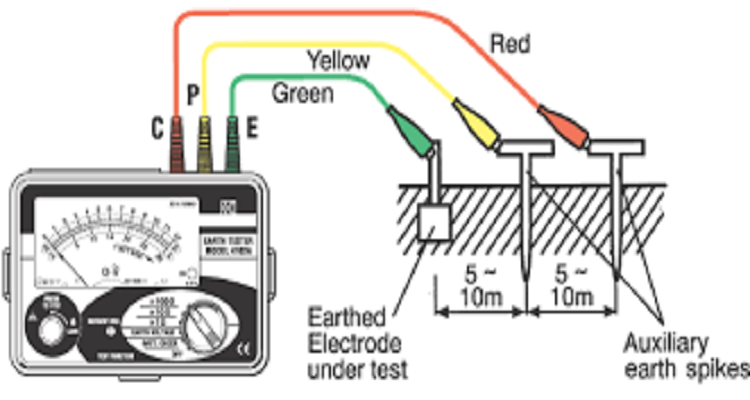
Wherever square tape clamps are installed it shall be ensured that two earth tapes are in proper contact with each other.
Earth tape shall be checked for good continuity, tightness and cleanliness.
Where it is necessary to form tape to tape joints, they shall be done by using thermo weld joint.
The down PVC / Single core conductor shall be laid from top roof through the RCC columns (which is indicated in the approved shop drawings) and clamped on the outer surface.
This shall be connected to top roof strip by clamp and then brought down till the junction box with test clamp.
From the test clamp junction box the conductor is connected to the earth pit, in the shortest possible route (As per specifications).
Earth pits shall be checked for recommended earth values and the same shall be recorded.
The earth electrode for the lightning protection system shall be connected below ground level to the earthing system earth pit through single core copper PVC sheathed cable.
After completion of installation and testing final connections shall be made after ensuring proper cleaning.
ATTACHMENTS
- Risk Assessment
- Inspection and test plan
- Quality control procedure
- Inspection Check sheets
Earthing & Bonding System Installation Package – Download Editable Files