
This plumbing method statement covers the installation of Sanitary, Vent and Storm drainage piping installation.
By following and implementing this procedure contractor shall ensure that drainage and vent piping have been installed as per the contract requirements and project specifications.
Required Materials
- PVC Pipe & Fittings
- Ductile Pipe & Fittings
- Cast Iron Pipe & Fittings
- Polyethylene Pipe and Fittings
- Polyethylene Film for Ductile & Cast Iron Pipes
- Rubber Gasket
Tools and Equipment Schedule
- Transit / Spirit Level
- Grinding Wheel Machine
- File
- String
- Leather Strap Wrench
- Carpenter Pincher
- Marker
- Leveling Hose
- Garden Hose
- Measuring Tape
- Hammer
- Manual Pressure Pump
Personnel Protective equipment: All personnel should wear at all time safety shoes, helmet and
Working Platforms: Scaffolding as required within the specific work area.
Storage and Handling
All materials stored on site are monitored by qualified storekeepers that ensure they are in good conditions and safe from environmental conditions that might endanger them ( e.g. moisture, heat, dust, friction).
Materials shall be stocked and stored in a safe confined space to prevent from deterioration and damage, the delivered material shall be checked to conform to the project specifications.
As for the handling, workers are instructed to carefully treat all equipment and materials with care and engineers as well as foremen monitor the material handling process for extra assurance.
Health and Safety
Health and Safety International Standards are always implemented on site through experienced health and safety officers and engineers so as to prevent danger and control safety hazards that might lead to serious injuries, it is compulsory to use an approved Personal Protective Equipment.
Environmental Requirements
All construction related works shall be executed to the highest levels of quality while at the same time avoiding any operation that might endanger the environment.
Therefore, materials are carefully chosen to be as environment friendly as possible.
Any hazardous material is carefully stored as mentioned earlier and scrap materials are carefully and safely disposed off.
Roles and Responsibilities
Mechanical engineers will monitor all work on site in order to ensure that all standards and specifications are being followed and that the work being executed is of the highest levels of professionalism and accuracy.
Quality Control engineer inspects and ensures the construction work is carried out according to project’s standards and specifications.
Safety Officer shall be responsible for the implementation Health and Safety aspects on site as per approved Health & Safety Manual requirements.
Foremen shall be present on site at all time to give out the correct instructions and coordination with the technician and other staff assign to his area, while ensuring the work required are being
implemented accordingly base on the Mechanical standard and project’s scheduled.
Qualified Technicians shall be responsible for a given undertaking and ensure the quality of works are well being executed progressively, while accurately considering the works base on project’s standards & specification.
The rest of the personnel consist of labors to aid the technicians, store keepers to ensure that the material stored is located in a safe environment with proper conditions of storage and safety officers who guarantee that all personnel are abiding by the safety rules and regulations of site work.
Installation of Underground Drainage Piping
Submittal / approval of drawings for construction.
Submittal / approval of materials.
Check availability of material and lead time to order material.
Keep the materials in good storage conditions, special care must be taken to protect the units from moisture, corrosion and dust.
Pipes must be stored horizontally with adequate support and handled with care when moving the material around.
Obtain excavation permit.
Trenching and Excavation for the installation of underground piping:
- Check for setting out and mark piping location on ground using pegs confirm the approved drawing.
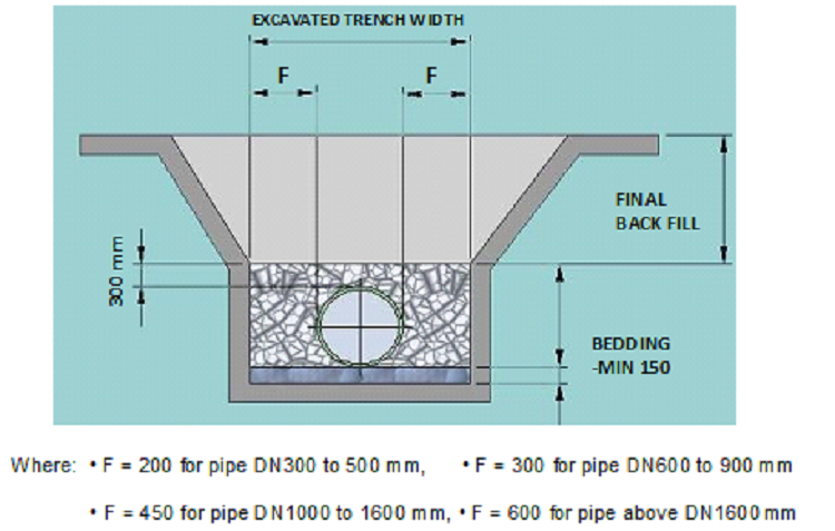
- Excavate trenches under building slab for 300mm cover over the pipe. A minimum of 600mm cover to be provided where pipe may be exposed to heavy overhead traffic.
- Shoring of trenches is to be provided if the excavation depth exceeds 1.5m.
- Barricade around the area that have been excavated on soft ground.
- Keep excavations dry wherever necessary.
- The pipes shall not rest on rock at any point, including joints.
- Side fill should be shoveled under the pipe to make sure that there are no voids in the side fill.
- The haunch areas adjacent to the pipe between the bottom of pipe and its horizontal centerline shall be filled with a clean course-grain materials such as sand, gravel, or soil. Such side fill shall be compacted to provide lateral support for the pipe.
Install Sanitary, Vent and Storm drainage piping at the following minimum slopes unless otherwise indicated.
- Building Sanitary and Storm Drain: 2 percent downward in the direction of flow for piping NPS 3 (DN 80) and smaller;1 percent downward in direction of flow for piping NPS 4 (DN 100) and larger.
- Horizontal Sanitary and Storm Drainage Piping: 2 percent downward in direction of flow.
- Vent Piping: 1 percent down toward vertical fixture vent or toward vent stack.
Make changes in direction for Sanitary, Vent and Storm drainage piping using appropriate branches, bends, and long-sweep bends. Use proper size of standard increasers and reducers if pipes of different sizes are connected. Reducing size of drainage piping in direction of flow is prohibited.
Clean pipes and fittings, removed oil, grease and any other loosely adhering deposits
Carefully unload required lengths and sizes of pipes to the work area.
Install pipes on the concrete pads making sure that they are secured in place and to the required slope.
Install following pipes and fittings as per its application:
For Sanitary and Vent piping:
| Area of Application | Material | Specified Descriptions | Size |
| Main Kitchens and Laundries Areas. (Underground, Soil, Waste & Vent Piping) | Hubless, Cast Iron Pipe & Fittings | ASTM A 888 or CISPI 301,
fittings: ASTM C 1277 and CISPI 310, ASTM C 1540, ASTM C 564 |
(DN 100) and smaller |
| Black Steel Pipe & Fittings | ASTM A 53/A 53M, Type E, Standard Weight class,
fittings: ASME B16.4, Class 125 |
(DN 50) and smaller | |
| All Areas, Underground, (Soil, Waste & Vent Piping), excluding Main Kitchen
and Laundries. |
uPVC Pipe & Fittings | Pipe: SASO 14 & 15, ISO 161/1, DIN 8061/62..
Fittings: SASO 1397, 1398, 1399,1400, ISO3633 /4435, EN 1401, BS 2494, |
Up to 630mm |
| Underground Sanitary- Sewage Force Mains | Ductile-Iron Pipe & Fittings | AWWA C151/A21.51,
fittings: AWWA C110/A21.10, AWWA C111/A21.11 |
All Sizes |
| Under ground Single- Wall, Acid-Waste Sewerage Piping Serving Battery
Charging Areas |
Polyethylene (PE) Pipe & Fittings | ASTM F 1412, Schedule 40,
fittings: ASTM D 3311 |
(DN 40 to DN 150) |
For Storm Drainage Piping:
| Area of Application | Material | Specs. Description | Size |
| Underground Storm Drainage Piping, Running Concealed or Exposed within Buildings | uPVC Pipe & Fittings | Pipe: SASO 14 & 15, ISO 161/1, DIN 8061/62.
Fittings: SASO 1397, 1398, 1399,1400, ISO3633 /4435, EN 1401, BS 2494 |
Up to 630mm |
| Underground Storm Drainage Force Mains | Ductile-Iron Pipe | AWWA C151/A21.51, with mechanical-joint bell and plain spigot end unless grooved or flanged ends are indicated. | All Sizes |
Lay buried building storm drainage piping beginning at low point of each system.
Install true to grades and alignment indicated, with unbroken continuity of invert.
Place hub ends of piping upstream.
Install required gaskets according to manufacturer’s written instructions for use of lubricants, cements, and other installation requirements.
Maintain swab in piping and pull past each joint as completed
Install encasement on piping according to ASTM A 674 or AWWA C105/A 21.5. applicable to Ductile pipe and Cast Iron pipe.
Check pipe straightness and invert level.
Drainage Pipe Leakage Testing
Test drainage and vent piping except outside leaders on completion of roughing-in.
Close openings in piping system and fill with water to point of overflow, but not less than 10-foot head of water (30 kPa).
From 15 minutes before inspection starts to completion of inspection, water level must not drop.
Inspect joints for leaks.
Test force-main piping at static-water pressure of 50 psig (345 kPa) above operating pressure, without exceeding pressure rating of piping system materials. See specifications.
Do not enclose, cover, or put piping into operation until it has been inspected and approved by authorities having jurisdiction.
Backfilling of pipe trench for installed underground piping:
- The side fill adjacent to the pipe must be backfilled and tamped to the top of the pipe.
- Initial backfill must be placed in 6” tamped layers. The use of heavy compacting equipment is prohibited.
- Maximum particle size in the side fill and initial backfill shall not more than ½ inch for pipe 6” size and smaller, and ¾ inch for 8” and larger.
- The initial backfill material must be sand, gravel, or loose soil from the excavation that is free from rocks and debris. Broken concrete, frozen earth, and other solid materials may damage the pipe from point loads.
- After the pipe is covered with 2 feet of tamped initial backfill, the final backfill to grade can be compacted with heavy equipment.
Conformance Criteria
The personnel on site shall ensure that the work done conforms to the Standard and the required specifications.
For this task, it consists of the following project standards / specifications:
Piping materials shall bear label, stamp, or other markings of specified testing agency.
Comply with following Local and International Standards.
- National Plumbing Code (NPC)
- International Plumbing Code (IPC)
For solvent cements and adhesive primers, documentation indicating that products comply with the testing and product requirements of the California Department of Health Services’ “Standard Practice for the Testing of Volatile Organic Emissions from Various Sources Using Small- Scale Environmental Chambers.”